
VIDEO
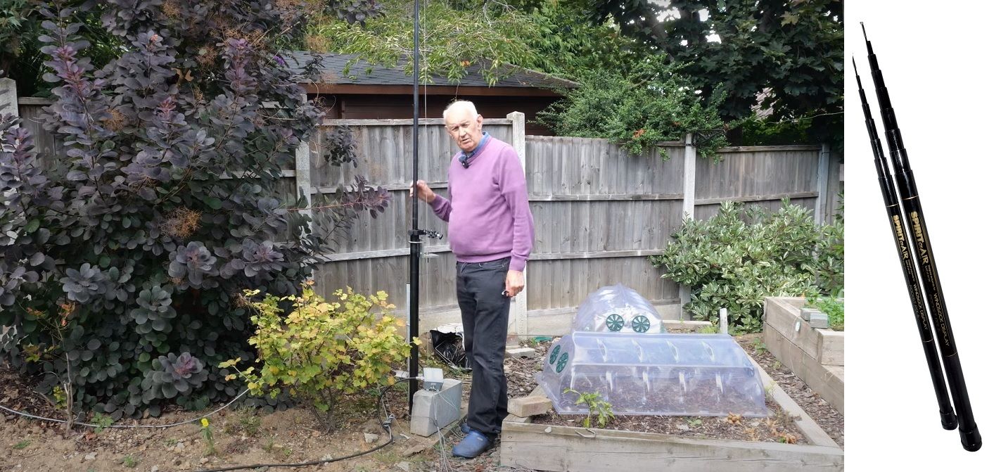
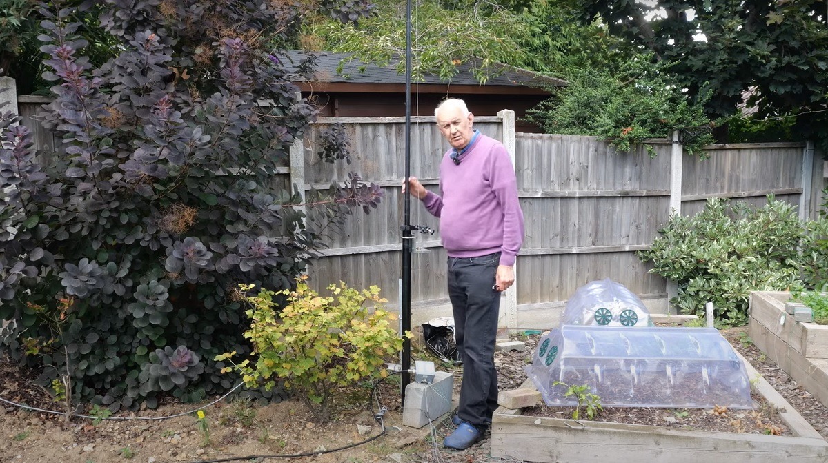
I'm Waters Stanton, and in this article I want to share an antenna I've been developing that solves a problem many hams face: how to get on the HF bands when your garden or backyard has restrictions, covenants or simply little space. I call it the "near invisible" HF vertical — a 13 ft (approximately 4 m) vertical that covers five HF bands (20, 17, 15, 12 and 10 metres). It's simple, inexpensive, discreet and surprisingly effective.
Why a near-invisible antenna?
From the messages I receive, it's clear a lot of people want to operate on HF but can't put up conventional outdoor antennas. Reasons vary: homeowners associations, covenants, landlord rules, compact gardens, or neighbours who object to tall masts. Loft antennas are a possible alternative, but lofts are often full of electrical wiring and switching supplies which makes noise a major issue. So for many of you the only practical option is something outside that is as unobtrusive as possible.
When designing this antenna my aims were straightforward:
- Small physical profile — not an obvious mast or huge wire spanning the garden.
- Works on multiple HF bands without traps or complex matching networks.
- Simple, cheap to build and easy to install, maintain and remove.
- Reasonable performance compared to a conventional antenna on the same bands.
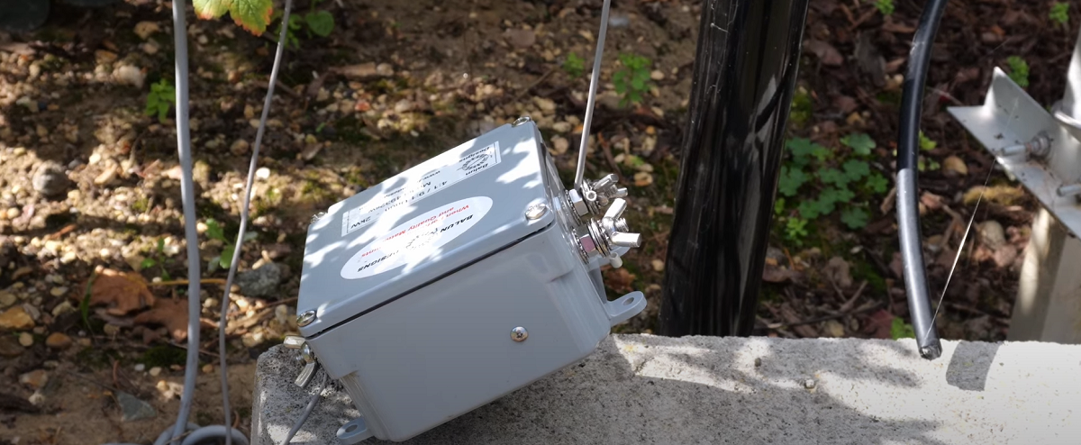
The solution I arrived at is a vertical element taped to a short fiberglass mast and fed through a 4:1 unun at the base. It’s not magic — it’s just careful experimentation with length and impedance so that the antenna presents a manageable, medium impedance across five bands.
The basic idea — 13 ft and a single wire
There are two broad families of HF antennas: horizontal and vertical (with inverted-V as an in-between). Horizontal antennas usually need height to work well; they require masts at each end or an elevated support that can be quite visible in a garden. Vertical antennas, by contrast, can be very compact and self-supporting. They do need a ground system (radials), but their visible profile can be far lower than a horizontal dipole or a multi-element beam.
What I found by cutting and trying lengths is that a single straight wire around 13 ft long, mounted on a telescopic or fixed fiberglass pole, radiates usefully on 20, 17, 15, 12 and 10 metres. If you feed this element with a 4:1 unun and arrange a few short radials on the ground, you end up with a practical multi-band antenna that is both inexpensive and unobtrusive.
""It's a 13 ft length of wire with a 4:1 unun at the base and fed with coax. The whole of the antenna works on all bands — there's no traps or anything like that.""
Key advantages
- Low visual profile — a 13 ft pole is far less noticeable than long horizontal wires or tall masts.
- Multi-band coverage from a single element — no traps or switching required.
- Simple construction and maintenance — tape the wire to the pole, fit a small unun at the base, lay a few temporary radials and you’re ready to go.
- Cheap to build — you can do this for roughly £60–£70 if you source a telescopic fiberglass pole and an LDG 4:1 unun (or make your own unun).
Materials and approximate costs
Here's what I used for my build and what you might expect to pay (prices approximate and dependent on region and suppliers):
- 7m telescopic fiberglass mast — telescopes down to a convenient height (I used one telescoped to about 13 ft). There are many cheap options available; I would budget about £20–£40 if you shop around.
- Wire for the vertical element — any insulated wire rated for outdoor use, cut to about 13 ft (4 m).
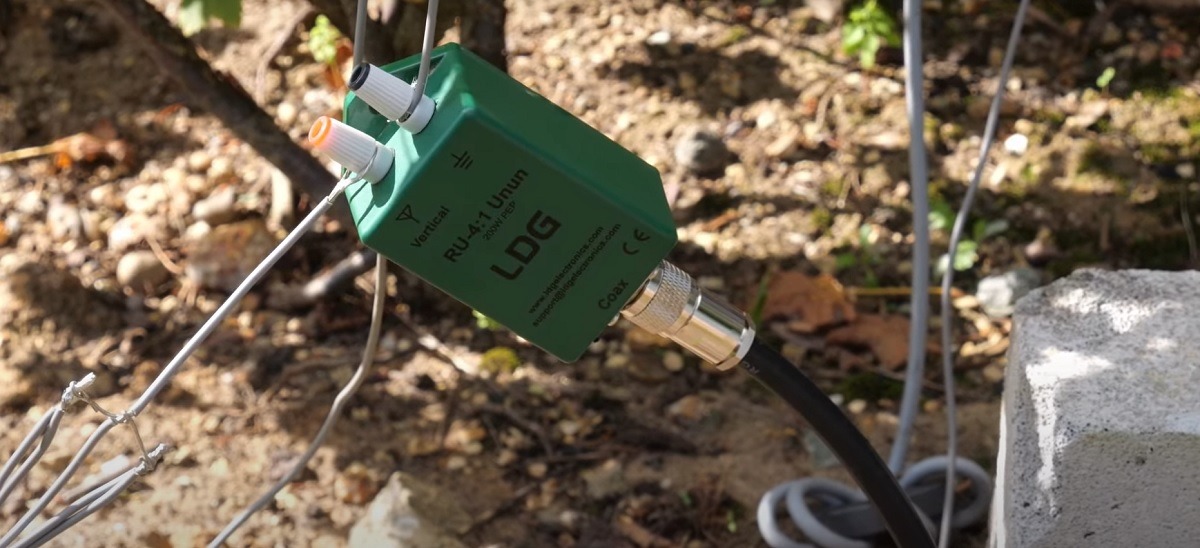
- LDG 4:1 unun (or equivalent) — around £30–£50 depending on the model; I used an LDG 4:1 unun for neatness and convenience.
- Coaxial cable — RG213 or similar for the run to the shack (choice influences loss), connectors and gland as needed.
- Short radials — I used several 2 m radials attached to a garden cane for easy handling.
- Insulating tape, cable ties, and waterproofing material — we’ll discuss a cheap and practical waterproofing method below.
All told, you can get on the air cheaply: the mast and unun are the priciest items. You could substitute a tree branch for the mast if you have one and wish to hide the setup completely, further reducing cost.
Construction : step-by-step
Building this antenna is deliberately simple. I’ll describe what I did so you can replicate it.
- Cut the element
- Cut a single piece of insulated wire to about 13 ft (4 m). This is the radiating element.
- Strip a short length at the base end for termination onto the unun.
- Mount the wire on the mast
- Tape or secure the wire along the length of the fiberglass mast. It does not need to be perfectly straight but avoid large loops or kinks.
- If you have a telescopic pole, extend it to the desired height (I used roughly 13 ft). Fiberglass poles are cheap and weather-resistant and do not require heavy duty strength — this is not a load-bearing mast.
- Fit the 4:1 unun at the base
- Attach the unun to the base of the mast and connect the element to the unun’s wire terminal.
- Connect the coax feed to the unun’s coax terminal. Make sure connectors are secure.
- Lay radials
- I used several short radials, 2 m long, attached to a garden cane for easy handling. Lay them roughly evenly spaced on the ground around the base.
- If you need to mow the lawn, simply lift the radials on the cane and put them aside while you cut the grass — they’re easy to move and re-deploy.
- You can add more radials if you have the space; more radials usually improve the match and efficiency, but the system will work with a modest number.
- Waterproofing and finishing
- Protect the unun from the weather. LDG ununs are not inherently waterproof. There are many ways to weatherproof electronics outdoors; I describe a cheap and effective method below.
- Tape any exposed wiring and use cable ties to prevent chafing.
Radials — how many and what length?
Radials are the ground return path for a vertical antenna. In a full-size installation you might lay many long radials, but for the near-invisible garden version you can use short surface radials. I used several 2 m radials and fastened them to a garden cane so they are easy to raise for lawn mowing and easy to keep tidy. A small number of short radials will get you on the air and deliver reasonable performance for a compact, low-profile installation.
Considerations:
- More radials improve efficiency, especially if you’re using short radials on the surface. If possible add more 2–3 m radials to get better matching and a bit more efficiency.
- Burying radials is an option (and can be more aesthetically pleasing), but you then lose the convenience of being able to check and move them. Surface radials are fine and easy to manage.
- Raised radials or a proper ground plane are an option if you want to further optimise — but these add complexity and visibility.
Matching: 4:1 unun and transceiver ATU
One of the clever parts of this design is choosing an element length that presents a roughly medium impedance on the bands of interest. It’s not a perfect match (you will not get a 1:1 VSWR), but the impedance tends to sit in a middle range rather than very high or very low. When you place a 4:1 unun at the feed, it transforms the impedance to a range your transceiver or internal ATU can handle.
Some notes on matching:
- You should expect VSWRs typically around 2:1 and up towards around 3:1 on the band edges. That’s not perfect but is manageable.
- Most modern transceivers include internal antenna matching units (ATUs). I tested this antenna with a Yaesu FT-710 and the new FT-1X (Optima) — both matched the antenna across the 20–10 m range without difficulty.
- If you have an older transceiver with no ATU, you might need an external ATU or a manual tuner at the radio to match. But my experience suggests a lot of modern rigs will cope.
- Losses due to VSWR on coax are often overestimated. Even with 2:1 or 3:1 VSWR the total loss on a short to moderate run of coax (e.g. RG213 or similar) at HF frequencies is
- modest — well under 1 dB in many practical cases depending on run length and cable type.
On-line calculators and real-world loss
If you’re worried about coax loss at elevated VSWR, use an on-line coax loss calculator. Enter your coax type, length, frequency and VSWR and you’ll see total loss figures. In my testing a realistic example using RG213 at HF with a 3:1 VSWR returned losses significantly below 1 dB across much of the bands in question — negligible compared to propagation uncertainties and other system losses.
Performance — what to expect
How well does this small vertical actually perform? To be honest, I was pleasantly surprised.
- On 20 m the 13 ft element is nearly a quarter wave so it performs very well for DX and local contacts. On 17 m it’s almost full size and remains highly effective.
- On 15, 12 and 10 m the element is over a quarter wave and performs well, though radiation pattern lobes change with frequency as you’d expect for an electrically longer element.
- I compared this antenna informally against a 4BTV (a popular multi-band vertical) and found the near-invisible 13 ft vertical to be remarkably close on 20 m, 15 m and 10 m in terms of reports and copy. Exact comparisons are hard because propagation constantly varies, but performance is good enough for enjoyable HF operation.
Important caveat about 40 m: this antenna does not cover 40 m. A vertical on 40 m often behaves unfavourably, giving low-angle lobes when high-angle radiation is needed during the day, and generally a horizontal dipole tends to outperform a small vertical on 40 m. So if you need reliable performance on 40 m, this design won't be the best choice unless further modifications are made (longer element, better ground plane, or trap/load modifications).
Measurement example: VSWR sweep
When I swept the antenna with an analyser, the VSWR across the 20–10 m range sat around 2:1 at centre and rose towards 3:1 on some band edges. That’s consistent with the idea that the antenna presents a medium impedance transformed by the 4:1 unun. The internal ATU on modern rigs handles that easily and, as noted, the loss on coax at those VSWR figures is small.
Getting extra transmit punch — running more power
One crude way to get more signal out on transmit when using a small or compromised antenna is simply to run more transmitter power. I’m aware this invites debate — more power can be dangerous if not applied with proper precautions, and local regulations must always be followed. But for those who can legally and safely increase power, a higher-power unun and a robust feed arrangement can raise your effective radiated power.
For my tests I wanted to try higher power. I sourced a higher-rated 4:1 unun (a unit rated at 2 kW). I didn’t run 2 kW, but I ran a few hundred watts (400–500 W) through that unun. What I observed:
- Transmit reports improved by roughly 1–1.5 S-points compared to 100 W, which is what you'd expect from a power increase.
- There was no improvement on receive (power doesn’t affect signal-to-noise on receive except through associated improvements such as better matching and reduced loss).
- Higher-power operation requires careful attention to safety (RF exposure, connector ratings, quality of coax and connectors, and local regulations). If you are going to run elevated power, use properly rated gear and take safety precautions seriously.
Waterproofing and practical maintenance tips
Any outdoor installation needs sensible waterproofing. LDG ununs are not always waterproof, so either buy a weatherproof enclosure or protect the unun. In the video I mentioned and continue to recommend the old ham DIY trick:
Cling film (plastic wrap) around the unun and connectors, with tape to seal, is an inexpensive and surprisingly effective short-term solution. Replace it annually or whenever it looks tired. For a more permanent solution, use a small waterproof junction box with a proper cable gland.
Other maintenance tips:
- Inspect coax connectors and the unun annually for corrosion or moisture ingress.
- Check the mast’s condition (fiberglass poles are pretty resilient but do age) and re-tape the element if the tape degrades.
- If you use the garden cane radial trick, keep the cane and radials tidy and ensure ties are secure before high winds.
Common questions and troubleshooting
Will my internal ATU always match this antenna?
Most modern transceivers with an internal ATU will handle the 2:1–3:1 VSWR range on these bands. I tested with the Yaesu FT-710 and the FT-1X Optima — both matched without trouble. Older rigs without an ATU may need an external tuner. If you have an ATU that struggles at higher VSWRs, consider a 1:1 current choke or additional ground radials to improve matching before the tuner.
How many radials do I need?
More radials are better, but for a garden installation several 2 m radials will get you started. The garden cane method is convenient because you can lift them to mow the lawn. If space allows, add more radials to reduce ground loss and improve efficiency.
Can I hide it from neighbours?
Yes. The whole idea of this antenna is low visual impact. A 13 ft pole is less likely to attract attention than a long horizontal wire or a tall multi-element tower. You can disguise it with a plant or place it behind garden features. If there are strict covenants, check local rules — I can't advise on legality for your area, only on low-visibility design.
Can I scale this design up or down?
The 13 ft figure is what worked well for the bands I targeted. You can experiment with slightly different lengths, but the impedance behaviour will change. If you make the element longer you may improve 20 m performance but change the impedance on the higher bands. The beauty of the 13 ft compromise is multi-band usability with a simple unun.
Safety and best practices
- Observe RF exposure guidelines when operating, especially if you choose to run high power near the house or where people may be nearby.
- Use properly rated coax and connectors. Poorly rated components can overheat at high power.
- Ensure the mast is secure and won't fall in wind or onto the house. Even short telescopic masts can suffer in bad weather if not tied off sensibly.
- Disconnect coax during electrical storms and follow local safety guidance for lightning protection.
Summary and final thoughts
If you want a low-cost, low-visibility way to get on multiple HF bands, the 13 ft near-invisible vertical is a compelling option. It’s not a miracle antenna — it won’t outperform a perfectly installed full-size dipole or a big multi-element beam on every band. But for restricted gardens, temporary setups, or anyone wanting a compact multi-band HF solution it delivers excellent value. It’s cheap, discreet and surprisingly effective on 20, 17, 15, 12 and 10 metres.
To recap the key points:
- 13 ft single vertical wire taped to a fiberglass mast provides multi-band coverage (20–10 m) with a 4:1 unun at the base.
- Short surface radials (2 m) laid on the lawn and attached to a garden cane make deployment and lawn maintenance easy.
- Expect VSWR in the region of 2:1 to 3:1 — most modern radios with ATUs will match this without difficulty.
- Performance is surprisingly close to larger verticals on several bands, though this design does not cover 40 m well.
- Waterproof the unun (cling film or a small junction box) and follow safety practices for power, grounding and lightning.
If you build one, experiment with radial count and arrangement; even small adjustments can improve matching and performance. And above all — enjoy ham radio. This simple, near-invisible antenna opens HF to many hams who otherwise struggle with space or rules, and that’s what makes it worth sharing.
73 and clear signals — I hope this helps, and I look forward to hearing about your experiences with a compact vertical of this kind.
For more information please visit our online store or alternatively contact us and our team will be happy to assist you!