
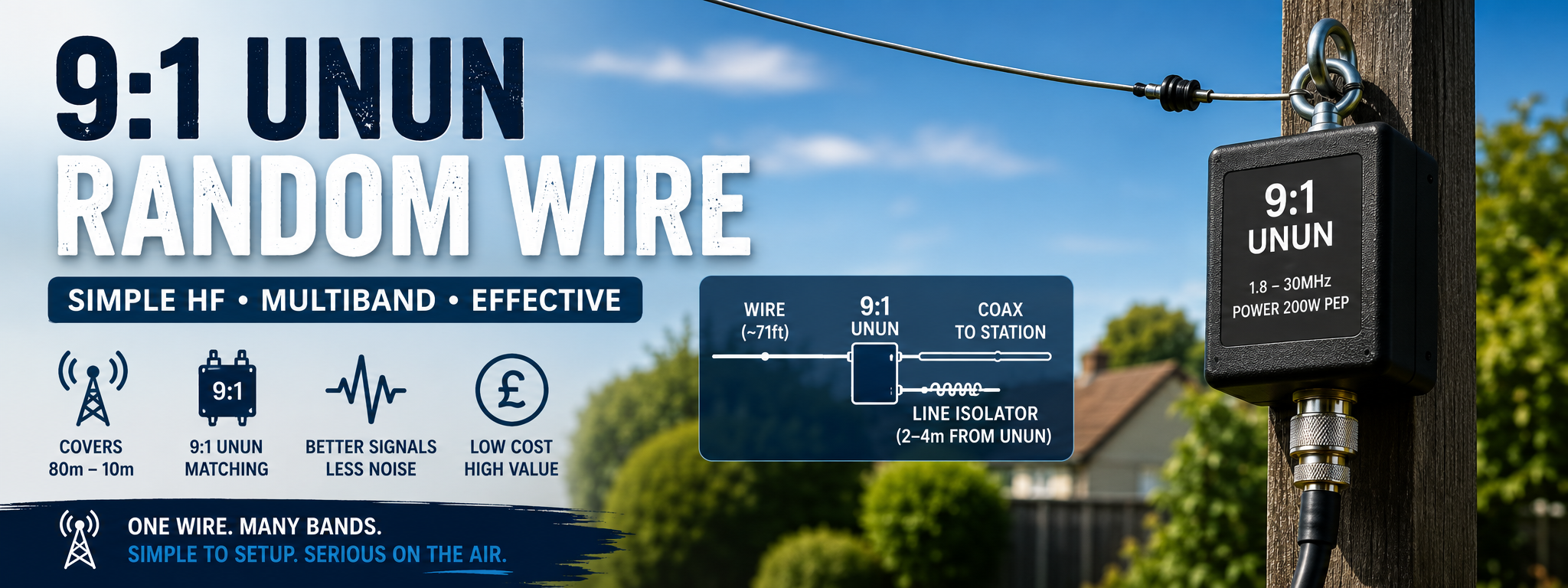
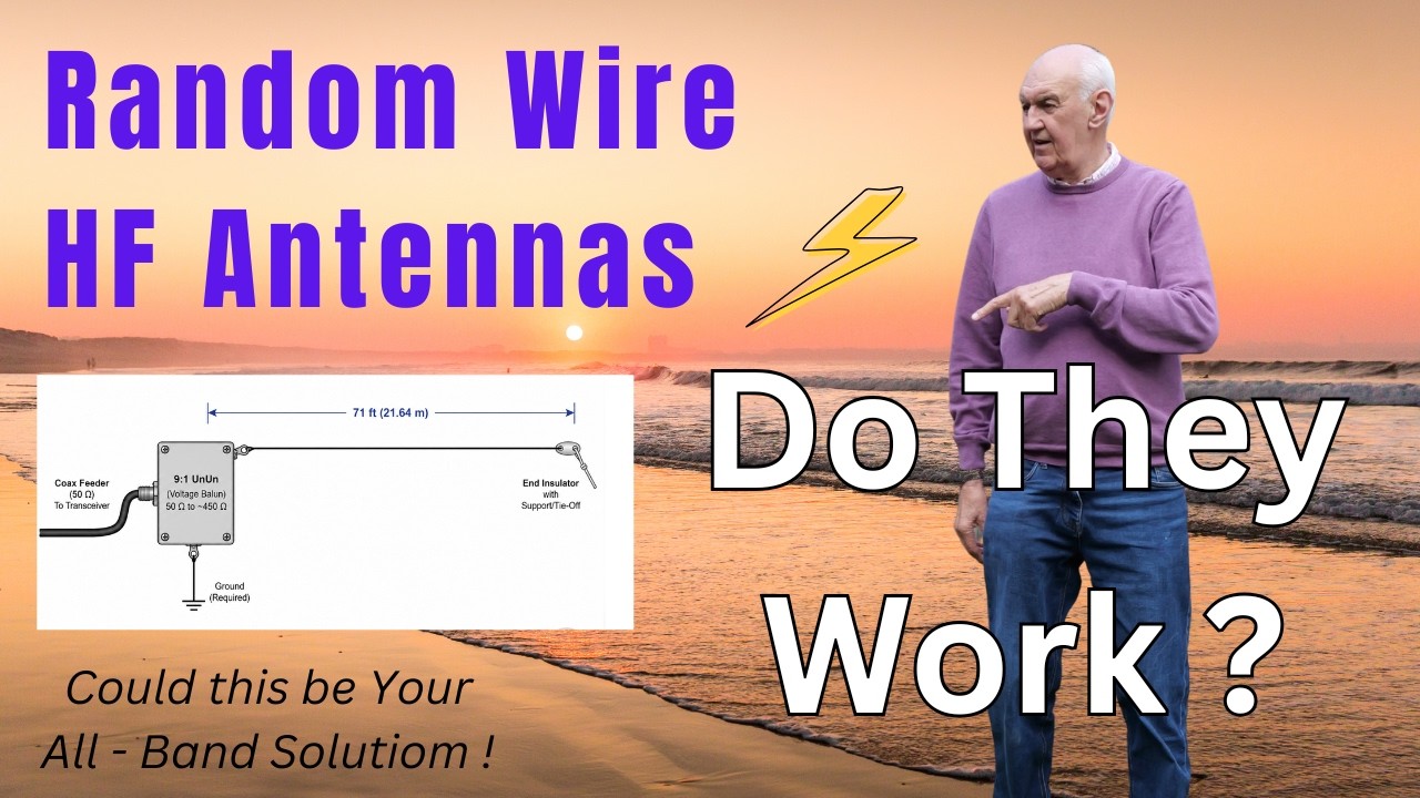
The 9:1 unun random wire end fed antenna has become increasingly popular, and it is easy to see why. It is simple, inexpensive, discreet, and capable of covering multiple HF bands with one length of wire.
That said, many radio amateurs still look at the phrase random wire with a fair bit of suspicion. Quite understandably too. If you have spent years thinking in terms of resonant dipoles, trapped antennas, and carefully cut wire lengths, the whole idea can sound a bit too casual to be taken seriously.
But this type of antenna does work, and in the right circumstances it works rather well. The trick is understanding what it is actually doing, what it needs to work properly, and where its limitations are.
Why the 9:1 random wire appeals to so many operators
For anyone wanting to get on the HF bands without erecting something large, heavy, or visually obvious, a random wire antenna has a lot going for it.
- It is simple. You need a length of wire, a 9:1 unun, and coax.
- It is affordable. Compared with many multiband antenna systems, the cost is modest.
- It is easy to install. Most gardens can accommodate some sort of wire run.
- It is low profile. A thin wire is much less conspicuous than many other antenna types.
- It can cover several HF bands. That makes it attractive for general operating.
- It is flexible. The wire does not have to be perfectly straight and can often be routed around obstacles.
Horizontal wire antennas also remain popular because many operators find them quieter than verticals, especially in noisier locations. Verticals certainly have their place, but for many domestic installations a wire antenna is often the easiest practical answer.
What “random” really means
The word random is probably the most misleading part of the whole subject.
This is not a case of cutting any old bit of wire, attaching it to an unun, and expecting miracles across every HF band. The wire length does matter. What people usually mean by a random wire in this context is a non resonant wire cut to one of several proven lengths that tend to avoid the worst impedance extremes on multiple bands.
So although it is called random, it is not truly arbitrary. It is better thought of as a convenient non resonant multiband wire.
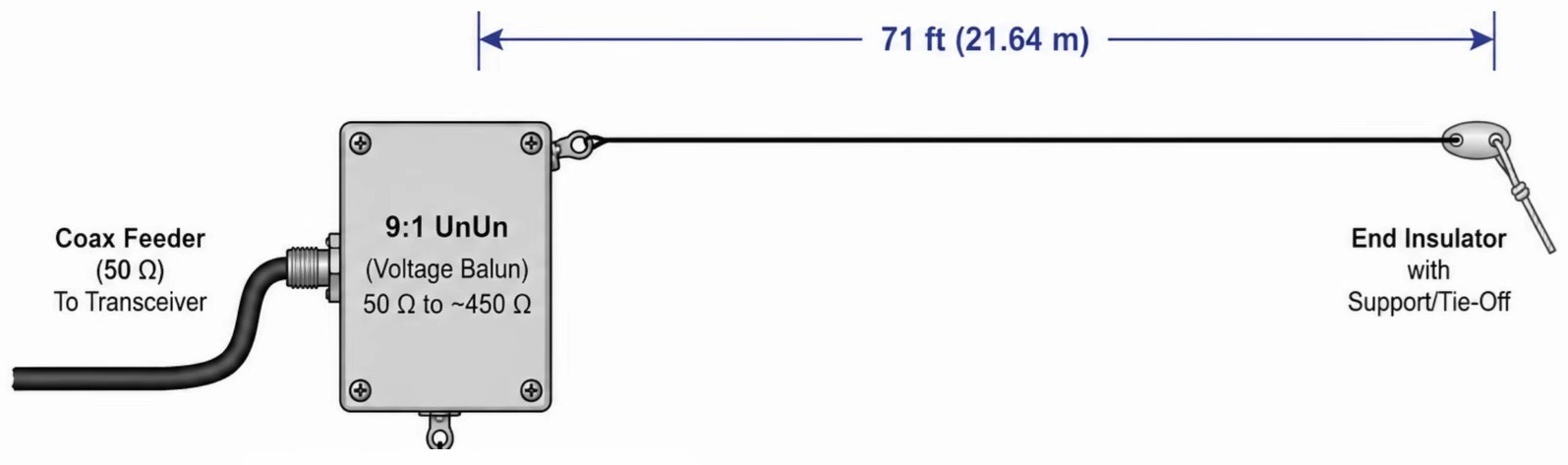
A practical example is a wire around 71 feet long, which is a very common starting point and suits many gardens nicely.
How a 9:1 unun random wire actually works
The operating principle is quite straightforward once you stop expecting the antenna to behave like a resonant dipole.
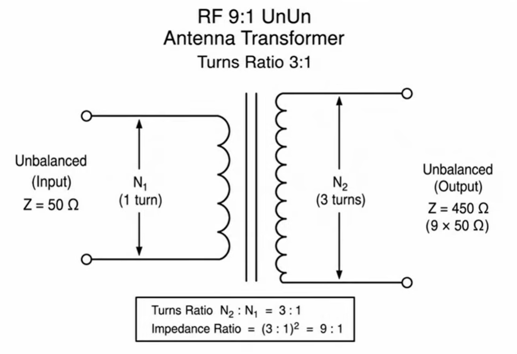
On the HF bands, a suitable length of non resonant wire often presents a medium impedance. Not 50 ohms, and not the very high impedance associated with an end fed half wave, but something in the region of a few hundred ohms. A rough figure of 400 to 600 ohms is a useful way to think about it.
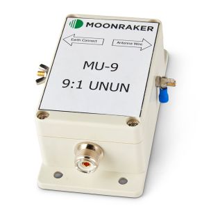
That is where the 9:1 unun comes in. It is there to transform that medium impedance to something much closer to what the transceiver and coax system can tolerate.
In other words:
- The wire provides a multiband radiating element.
- The impedance is often in a moderate range on several bands.
- The 9:1 unun transforms that impedance downward.
- The transceiver, often with help from an ATU, can then load it successfully.
It is not a perfect match on every band, and that is an important point. This is a practical antenna, not a magical one.
The basic layout
A typical 9:1 random wire end fed antenna system is very simple:
- A length of wire cut to a recommended starting length
- A 9:1 unun at the feed point
- A coax cable run back to the station
- One or more line isolators or common mode chokes
- Often an antenna tuner, especially for lower bands
The wire itself can be run horizontally, sloped, bent around the garden, or arranged with a vertical and horizontal section if that suits the space available. The main thing is to start with a sensible wire length rather than simply using whatever happens to be lying about.
It is not quite a true end fed
This is one of the most important things to understand.
Although the antenna is often described as an end fed wire, the coax shield also plays a part in the system. In practice, the coax becomes part of the counterpoise. So electrically, the arrangement behaves more like a two sided antenna system than a single isolated wire.
That is why common mode current management matters.
One “side” of the antenna is the wire running out into the garden. The other “side” is effectively part of the coax run. This is also why line isolators can be useful, because they help define how much of the coax is allowed to participate in the radiating system.
Why line isolators matter
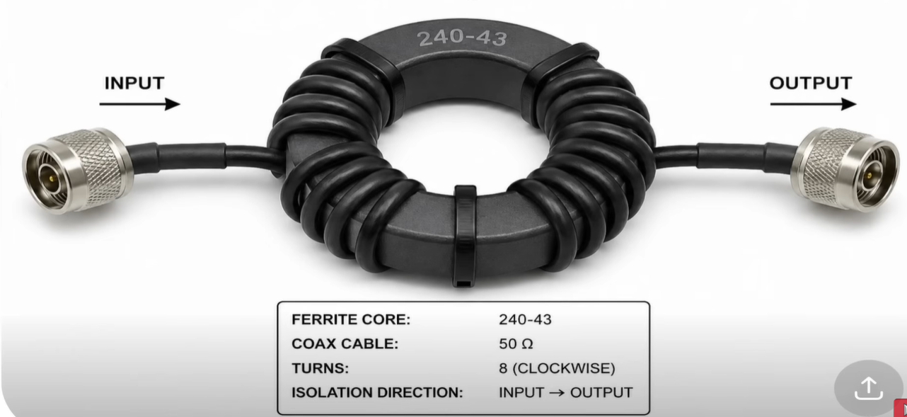
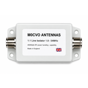
A line isolator, or choke, is a useful addition to this type of antenna system. It is typically made by winding coax around a ferrite core, or by using a purpose made common mode choke.
The idea is to control RF current flowing back down the outside of the coax. A commonly suggested approach is to place the first isolator a short distance from the unun. A useful rule of thumb is around 0.05 wavelength of the lowest intended operating frequency.
For a setup aimed mainly at 40 metres through 10 metres, that works out to roughly 2 metres of coax from the transformer to the first line isolator.
However, if you also want to make the system useful on 80 metres, a distance of around 4 metres is a more sensible starting point.
That effectively gives you:
- The main wire as one side of the antenna
- A controlled short section of coax as the other side
- The isolator preventing the rest of the feedline from becoming heavily involved
Because there can be a fair amount of RF moving about in these systems, it is also wise to place another line isolator near the equipment end of the coax, as close as possible to the first item in the station chain. That could be the ATU, an SWR meter, or the transceiver itself.
Do you need an antenna tuner?
In many cases, yes.
This is one of the places where expectations need to be realistic. A 9:1 random wire end fed antenna often does not present a beautifully low VSWR across every band. On some bands the match may be quite decent. On others you may see something around 2.5:1 or 3:1.
That sounds alarming to some people, but on HF the associated loss is usually not dramatic. The bigger issue is whether the transceiver is happy with that mismatch.
Some internal tuners are quite capable. Certain modern transceivers have rather good built in matching units and may cope well on several bands. Others may struggle, especially on 40 metres or 80 metres.
An external ATU generally offers a wider matching range and can make the difference between an antenna that is merely interesting and one that becomes genuinely useful every day.
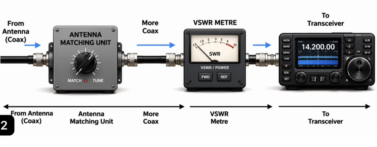
A practical station chain often looks like this:
- Coax from the antenna
- Line isolator near the station end
- External antenna tuner
- SWR meter if required
- Transceiver
If the tuner already includes an SWR meter, the setup can be even simpler.
Real world performance over a year of use
A good test of any antenna is whether it stays in service after the novelty wears off.
In this case, replacing a half size G5RV with a 71 foot random wire fed through a 9:1 unun turned into a much longer trial than expected. The plan may have been to test it and then put the old antenna back, but the random wire ended up staying in place for about a year because it proved itself surprisingly well.
On the air, it has worked effectively from 80 metres through 10 metres when used with a suitable ATU.
Some practical observations stood out:
- 20 metres through 10 metres were generally easy to match.
- 40 metres could be a bit more awkward.
- 80 metres was quite usable in the evenings with an external tuner.
- Even low power contacts on 80 metres were possible.
- 160 metres was outside the comfortable range of the usual tuner with a 71 foot wire, though a more capable matching network could sometimes load it.
That last point is useful. If operation on the lower bands is important, then a longer wire is generally the better route. The 71 foot length is a compromise, not a miracle solution for top band.
What about radiation pattern and noise?
No horizontal wire of this sort is truly omnidirectional, so it would be wrong to describe the antenna that way. There will be lobes and nulls, and the exact pattern depends on height, length, band, and the shape of the installation.
Even so, in ordinary use it can provide broad and practical coverage. Contacts in many directions are perfectly achievable, and in day to day operating there may be no obvious sense that it is badly favouring one part of the world over another.
As for noise, one of the pleasant surprises with this type of horizontal wire setup is that it can be very civilised. In use, there may be no obvious noise penalty and no particular reports of interference either, provided the system is installed sensibly and common mode currents are kept under control.
Do not treat the wire length as sacred
This is another important practical point.
Recommended wire lengths are just that: recommended starting points. They are not universal laws. Every antenna is influenced by its surroundings, including:
- Nearby buildings
- Trees
- Ground conditions
- Installation height
- The exact route the wire takes
So if your chosen length does not perform quite as hoped, do not be afraid to alter it slightly. A small change in the radiating wire can improve things noticeably.
An antenna analyser is extremely useful here because it lets you see what the antenna is doing across the bands rather than relying on guesswork.
Interestingly, practical experimentation suggests that adjusting the wire element tends to have more effect than fussing endlessly over the feedline length. In fact, it is entirely possible to simplify things and still get good results, provided you keep proper isolation at the station end.
A sensible starting setup
If you want a straightforward way to try a 9:1 random wire end fed HF antenna, this is a sensible starting recipe:
- Choose a known good wire length such as 71 feet.
- Use a decent 9:1 unun rated appropriately for your power level.
- Run the wire in whatever shape best suits your space.
- Place a line isolator a few metres down the coax, especially if 80 metres is desired.
- Place another isolator near the station entry or just before the equipment.
- Use an external ATU if your transceiver’s internal tuner cannot cope on some bands.
- Check the results with an antenna analyser and trim the wire if necessary.
Is it a sensible all band antenna choice?
Yes, with a bit of common sense.
If by all band antenna you mean a single simple wire that gives useful HF coverage from 80 metres to 10 metres, is inexpensive, and can fit into an ordinary garden without attracting too much attention, then the 9:1 unun random wire is absolutely a sensible option.
It is especially attractive for:
- Beginners wanting a first practical HF antenna
- Operators with limited space
- Those needing a low profile installation
- Anyone wanting an easy multiband wire antenna to experiment with
The main cautions are equally clear:
- Do not assume any wire length will do.
- Do not expect perfect SWR on every band.
- Do not ignore the role of the coax and common mode currents.
- Do not be surprised if an external antenna tuner improves things significantly.
Used with realistic expectations, this is not a gimmick antenna at all. It is a serious, effective, low cost HF solution that can give very satisfying results across multiple bands.
And really, for a single wire in the garden and a small matching transformer, that is a rather impressive outcome.
Our Antenna Wire Selection:
-
 Original PVC Flexweave Antenna WireAs low as £1.20
 -
 KEVLAR 28 Heavy Duty Antenna wireAs low as £1.50
 -
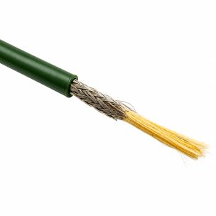 KEVLAR 32 Heavy Duty Antenna WireAs low as £1.75

Our Baluns, Traps And Ferrites Selection:
-
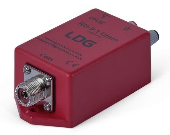
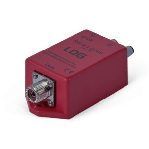 LDG RU-9 9:1 200 Watt Unun£34.99
 -
 Moonraker MV-9 (9:1 400W) UnunSpecial Price £29.95 Regular Price £34.95
 -
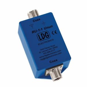 LDG RU-1:1 Unun£34.99
 -
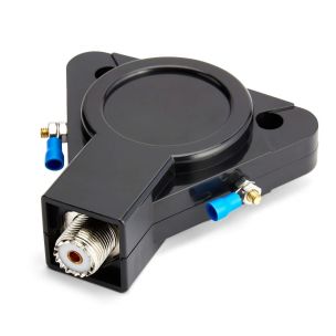 MB-4X - High Power 4:1 Current BalunSpecial Price £29.95 Regular Price £34.99


Our Cables Selection:
-
 RG213 Mil Spec (50 OHM) CoaxAs low as £1.75
 -
 RG58 Standard (50 OHM) CoaxAs low as £0.45
 -
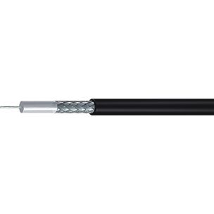 RG58 Mil Spec (50 OHM) CoaxAs low as £0.60
 -
 Mini8 Mil Spec (50 OHM) CoaxAs low as £0.90
 -
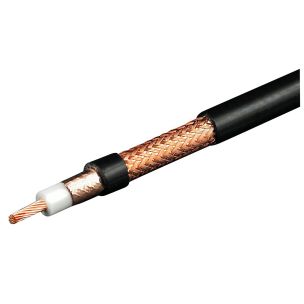 M&P - Ultraflex 10C (Competition) CoaxAs low as £3.25
Our Line Isolators And Antenna Tuners:
-
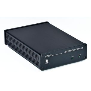
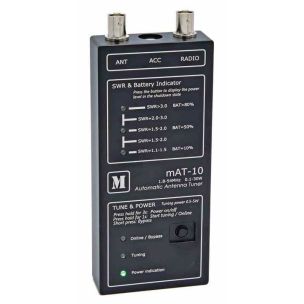 mAT-10 Automatic Tuner For QRP TransceiversSpecial Price £169.95 Regular Price £179.99
 -
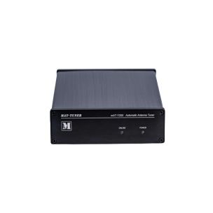 mAT-Y200 - Automatic Tuner (For Use with Yaesu)Special Price £209.95 Regular Price £229.99
 -
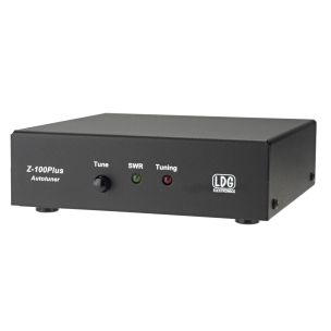
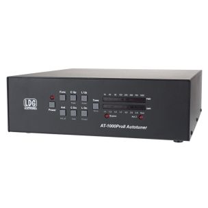 LDG AT-1000 PRO II - Automatic Antenna TunerSpecial Price £579.95 Regular Price £599.95
 -
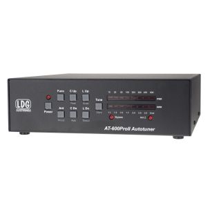 LDG AT-600 PROII - Automatic Antenna TunerSpecial Price £429.95 Regular Price £449.95
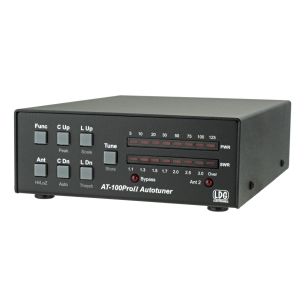

For more information please visit our online store or alternatively contact us and our team will be happy to assist you.