


Measurements are an everyday part of amateur radio: power, signal strength, voltage, current. But nothing causes more head-scratching than VSWR. Read on for practical explanations of several common VSWR surprises and what to do about them.

Image: Typical Quarter Wave Vertical
Why adding radials to a vertical can increase VSWR
It is common to assume that any improvement to the ground system will make everything better. Yet you may find that adding radials to a vertical antenna actually causes the measured VSWR at the shack to rise. That sounds wrong, but there is a straightforward electrical explanation.
A typical quarter-wave vertical often has a low intrinsic feedpoint impedance — roughly 20 to 25 ohms. The return half of the antenna system is the earth, and the earth presents a series resistance in the feed. If that earth resistance is relatively high (for example, a simple ground rod or poor ground contact), it can increase the apparent feedpoint impedance so that the combination of antenna plus earth resistance comes closer to 50 ohms. In that case the VSWR measured at the transceiver can look deceptively good.
When you add a radial system and improve the ground, you reduce that earth resistance. The true antenna impedance (the low 20–25 ohm part) is no longer “masked” by the high soil resistance, so the apparent impedance seen at the shack drops. The result: VSWR goes up. The good news is that the antenna is more efficient because less power is lost in the earth.
"If you add radials and lay them on the ground, that actually lowers the earth resistance... the antenna is more efficient. It's one of those anomalies where the VSWR rises, but the efficiency of the antenna goes up."
Why changing coax length can help an antenna tuner
A problem many face is a tuner that struggles to find a match on certain bands. One counterintuitive fix that often works is changing the coax length. Why? Because the impedance and reactance presented at the radio end of a feedline depend on line length and frequency.
The feedline transforms the antenna's complex impedance along its length. A particular length of coax may present a reactance the tuner finds hard to cancel. Adding or subtracting roughly an eighth of a wavelength of coax can change that transformed impedance enough for the tuner to cope. If you have trouble, experimenting with an extra section of coax (even laid on the floor) often cures the issue.

Mag-mount mobile antennas: why placement and cable routing matter
Mobile installations with magnetic mounts can show wildly variable VSWR when the mount or cable is moved. That frustrating behaviour usually comes from multiple RF return paths: currents flowing on the vehicle roof or trunk plus currents on the coax shield. These paths interact and shift the antenna's effective feed conditions.
The simplest cure is a choke or line isolator made from ferrite. Place the ferrite core where the coax enters the transceiver; this is often the most effective position. On occasion the ferrite at the aerial end helps too. Use a high-permeability mix suitable for HF (many operators use a mix like FX43 for these purposes).
"With a magnetic mount you can get strange VSWR results. The cure is to use a ferrite core... putting the ferrite where the coax goes into the transceiver usually resolves the problem."
Why better coax can make VSWR appear worse
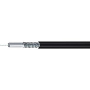
Swapping cheap RG58 for higher-quality, lower-loss coax and then seeing VSWR increase is another common source of worry. This is not because the antenna became worse; it is because the measurement became more accurate.
All coax has some loss. Cheap coax usually has higher loss, which attenuates both the forward and reflected waves. That attenuation can mask the actual reflected power, making the apparent VSWR at the radio look better than it truly is at the antenna feedpoint. When you use better, low-loss cable, less of the reflected energy is absorbed by the line, so the reflected wave reaches the radio more faithfully and the VSWR reading increases. The trade-off is positive: less loss in the feedline means more power radiated and improved overall system performance.




Useful measurements and a recommended tool
Understanding these behaviours is easier when you can measure impedance, reactance, and SWR across a swept frequency range. A compact antenna analyser is an excellent investment for home and field use. Look for a calibrated device with a graphical display that can:
- Plot VSWR or return loss across an HF range.
- Show reactance and resistance at specific frequencies.
- Measure coax length and identify faults on a reel.
- Operate portably so you can adjust an antenna and see results immediately without returning to the shack.
Modern analysers also highlight ham bands on the sweep and include detailed manuals that make learning much easier. They speed up tuning, troubleshooting, and antenna development, and they last for many years if treated sensibly.
-
 Discontinued RigExpert AA-35 ZOOM (0.06-35MHz) AnalyserSpecial Price £225.00 Regular Price £299.95Out of stock
 -
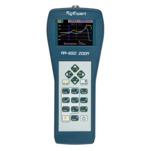 RigExpert AA-650 ZOOM (0.01-650MHz) AnalyserSpecial Price £550.00 Regular Price £679.95
 -
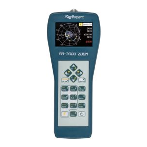 RigExpert AA-3000 Zoom (0.1 to 3000MHz) AnalyserSpecial Price £1,099.95 Regular Price £1,199.95Out of stock
 -
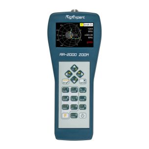 RigExpert AA-2000 ZOOM (0.01-2000MHz) AnalyserSpecial Price £999.95 Regular Price £1,099.95
 -
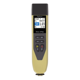 RigExpert Stick XPro (0.1 - 1150MHz) AnalyserSpecial Price £449.95 Regular Price £499.95Out of stock
Practical checklist: what to try when VSWR looks odd
- If VSWR rises after adding radials: remember it may be a sign of improved ground efficiency. Measure radiation performance, not only VSWR.
- If your tuner struggles: add an extra length of coax around an eighth wavelength and recheck. Small length changes can transform the tuner’s task.
- For mobile mag-mount issues: fit a ferrite line isolator at the point the coax enters the radio. Experiment with position if needed.
- After upgrading coax: expect a truer VSWR reading. Benefit from lower feedline loss and more radiated power.
- Use an antenna analyser: sweep the band, view impedance and reactance, and tune where it matters — at the antenna.



Final Thoughts
VSWR is a measurement, not the whole story. Higher measured VSWR does not always mean worse performance. Understanding the roles of ground losses, feedline transformation, common-mode currents, and coax attenuation helps turn puzzling readings into usable diagnostics. Spend a little time with a good analyser, try the simple fixes above, and you will get more reliable performance from your antennas and tuners.
For more information please visit our online store or alternatively contact us and our team will be happy to assist you!