

VIDEO

If your HF station uses coax from the transceiver to the antenna, you are probably bringing back more than you think. A simple item like a line isolator can clean up the shack, improve measurement accuracy, and prevent a whole category of frustrating “why is this happening?” problems.
Let’s go through what line isolators do, why they matter, how common mode currents cause trouble, and how to tell if you actually have a serious issue.
Why you might need a line isolator
With an HF transceiver connected to the antenna via coax, some RF energy inevitably returns into the shack. The key problem is not what travels along the coax centre conductor, but what travels on the outside of the coax braiding.
When RF gets onto the outside of the feed line, it can cause a cascade of issues:
- Incorrect VSWR readings (especially with external SWR meters and antenna analysers)
- Misleading VNA traces that make antenna tuning adjustments confusing
- Mobile installation headaches where moving the coax changes the resonance and SWR wildly
- More receive noise because the outside of the coax acts like a long wire aerial
- RF in the shack that can distort audio and interfere with transmit audio paths
- ATU problems where an antenna tuning unit struggles to reach a match
One of the most annoying parts is how “silent” the cause can be. You may feel like you’re doing everything right, yet the numbers look wrong or behaviour changes when you touch or move the feed line. A line isolator can stop those symptoms by addressing the root cause.
Common mode currents: the real culprit
To understand the fix, it helps to picture coax as two relevant “paths” for RF:
- The inside of the coax: the centre conductor and the braiding inside the shield carry the intended RF current to the antenna and back. (Refer - Blog)
- The outside of the coax: when the antenna drives the feed line, RF can also ride on the outer surface of the braiding. This is the unwanted part, because it behaves like an additional radiator or receiving structure.
RF energy travels on the surface of conductors. That is why the outside of the coax can pick up and carry RF differently from the RF that is supposed to flow within the coax structure.

Image: LDG RU 1:1 - (Buy Here)
How a line isolator works
The job of a line isolator is straightforward: block the RF on the outside of the coax while allowing the desired signal on the inside to pass normally.
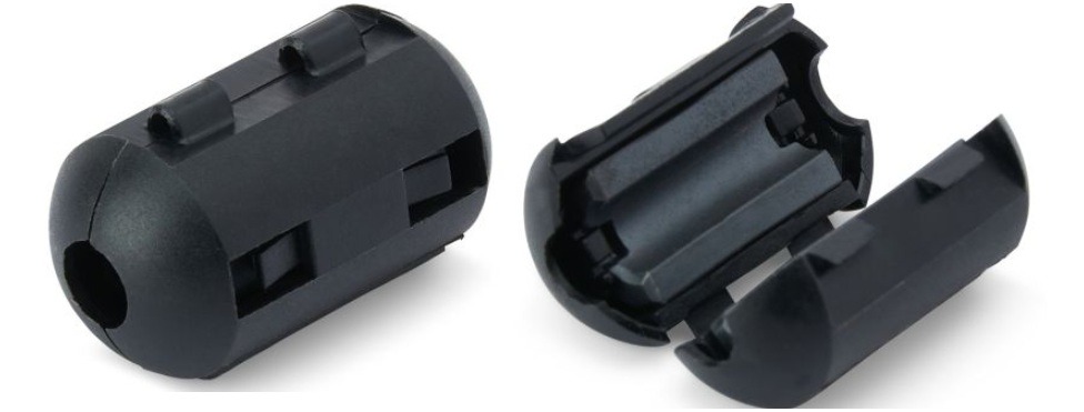
Most practical line isolators use a ferrite choke. The coax is wound through or around a ferrite core for several turns. That provides impedance to common mode currents on the outside of the coax, choking them so they can’t flow back into your shack.
The important idea is that ferrite cores are good at suppressing the unwanted current path, not the intended RF transfer.
Can you make your own line isolator?
Yes. One common DIY approach is to wind a few turns of coax around a ferrite core.

Image: Ferrite Ring 240-43
Why not just coil coax?
People sometimes try coiling extra coax as a “choke”. It can work but is often frequency sensitive. A coil can resonate at certain points, meaning it may perform well only over a limited part of the HF spectrum.
A ferrite choke is usually the more reliable solution.
A practical ferrite-core approach
A useful starting point is to use ferrite cores such as mix 43. A typical DIY configuration many operators use is:
- 10 to 12 turns around a ferrite core
- Often enough to cover common HF bands (for example, from 80 m up to 10 m or 6 m)
If you are running high power, you may worry about how many turns you can fit. A tip that helps: you do not necessarily need very thick coax for the choke windings.
Even with something like a linear producing around 700 W, you can still wind thinner coax (depending on your core and setup). In practice, the choke is a short length of coax, and losses can be negligible if built sensibly. Using reasonable quality coax and keeping the winding straightforward is usually sufficient.
How to tell if you have RF on the outside of the coax
You can’t always “see” common mode currents, but you can test for them. The goal is to check whether your feed line behaviour changes when you deliberately affect the connector or the outer coax current path.
-
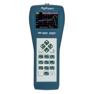 RigExpert AA-650 ZOOM (0.01-650MHz) AnalyserSpecial Price £550.00 Regular Price £679.95
 -
 RigExpert AA-1500 ZOOM (0.01-1500MHz) AnalyserSpecial Price £849.95 Regular Price £899.95
 -
 RigExpert AA-2000 ZOOM (0.01-2000MHz) AnalyserSpecial Price £999.95 Regular Price £1,099.95
 -
 Chelegance NANOVNA-F V3 VNA 6GSpecial Price £279.95 Regular Price £299.95

Test using an antenna analyser or VNA
If you have access to a VNA or antenna analyser that displays a VSWR trace:
- Connect the analyser to the coax at the point you would normally connect to the transceiver.
- Run a scan and note the shape of the VSWR curve.
- Now hold the PL259 or BNC plug firmly (don’t just lightly touch it). Keep your hand steady and compare the trace to the first measurement.
If the displayed curve changes significantly when you touch the connector, that is a strong sign you have a serious common mode current problem. In other words, your hand is altering the current flow on the outside of the coax.
This test is particularly revealing for mobile installations, where coax routing and the vehicle environment can encourage RF return paths.

A simpler VSWR-meter test
If you only have a basic VSWR meter, you can still try a low-power method:
- Run low power (for example 3 to 4 W) up the coax.
- Measure the VSWR.
- As you do so, grip the connector where it enters the VSWR meter (on the antenna side).
- If the VSWR changes when you touch, you likely have RF on the outside of the feed line.
Extend the coax and compare
Another practical check is to repeat your measurement:
- Measure VSWR with your normal coax.
- Add an extra 10 to 12 feet of coax as a patch lead.
- Measure again.
If the VSWR changes noticeably, that strongly suggests the outside of the coax is participating and acting like part of the RF system.
Where to install the line isolator
A line isolator should typically be fitted as close as practical to the transceiver, or at least before the coax enters the equipment cabin/shack area.
For mobile use, placing it before the coax goes into the transceiver is a sensible approach.
The point is to choke common mode currents early, so they do not run around your station creating noise and measurement confusion.
Real-world symptoms a line isolator can fix
Even if you cannot measure common mode currents directly, these are common “tells”:
- Mobile antenna resonance shifts when you move the coax. One moment it looks resonant, then resonance “goes all over the place”. A line isolator can restore stability so you can tune confidently.
- An ATU struggling to match on a band. Adding a line isolator can sometimes make the match achievable without endless fiddling.
- Noise levels rise compared to expectations, suggesting the feed line is acting like an unintended aerial.
- RF distortion on transmit audio where the signal sounds wrong and the cause is not the transmitter itself, but RF getting into audio or microphone leads.
In many cases, the operator spends an hour or more chasing a problem that “doesn’t make sense” until the feed line behaviour is corrected. Once isolated, the antenna adjustments finally behave the way the measurements should.
Conclusion
A line isolator is one of those ham radio upgrades that can be hard to “feel” immediately if everything is already clean. But if RF is getting onto the outside of your coax, it can prevent incorrect VSWR readings, reduce noise, minimise RF in the shack, and make antenna tuning (especially mobile tuning) far more predictable.
If you use coax with an HF transceiver, it is usually good practice to fit one and eliminate the guesswork.
For more information please visit our online store or alternatively contact us and our team will be happy to assist you.